
Digital Triaxial Shear Test Apparatus Manual
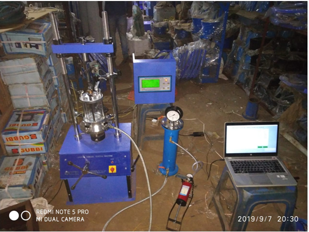
Digital Triaxial Shear Test Apparatus
Model No. SET-1001WARNING
Triaxial Shear Test Apparatus to reduce the risk of injury, all operators and maintenance personnel must read and understand these instructions before operating, changing accessories, wiring of machine or performing maintenance on SE-Test Lab Instruments. All possible situations cannot be covered in these instructions. Care must be exercised by everyone using, Maintaining or working near this equipment.
Digital Triaxial Shear Test Apparatus Safety
- The below safety instructions must be followed to avoid any property damage, personal injury.
- These machines must be operated by well-trained personnel and for its intended purpose only.
- Don’t make excess water pressure thought the foot pump.
WARNING: For safety, disconnect the power when performing any maintenance and/or cleaning.
Dig ital Triaxial Shear Test ApparatusInstallation:
- Install Load fame with front handle and side lever.
- Connect Load Cell on the top of Load Frame and LVDT on right side of Load Frame and both of thing will be connect with digital indicator.
- Set Triaxial cell on the top of machine& connect with pressure sensor with digital indicator, triaxial cell connect with lateral pressure assembly.
- Connect all sensor with digital indicator with computer system and install software and start operating the machine.
How to Conduct Test
Objective
The tri-axial shear test is most versatile of all the shear test testing methods for getting shear strength of soil i.e. Cohesion (C) and Angle of Internal Friction (Ø), though it is bit complicated. This test canmeasure the total as well as effective stress parameters both. These two parameters are required fordesign of slopes, calculation of bearing capacity of any strata, calculation of consolidation parametersand in many other analyses. This test can be conducted on any type of soil, drainage conditions can becontrolled, pore water pressure measurements can be made accurately and volume changes can bemeasured. In this test, the failure plane is not forced, the stress distribution of failure plane is fairlyuniform and specimen can fail on any weak plane or can simply bulge.
Apparatus Required
- Triaxial Shear Test Apparatus
- Rubber Ring
- Open ended cylindrical section
Scoop
This method determines the unconsolidated, undrained, compressive strength of cylindrical specimens of cohesive soils in an undisturbed condition, using a strain- controlled application of the axial compression-test load where the specimen is subjected to a confining fluid pressure in a triaxial chamber.
The method provides for the measurement of the total stresses applied to the specimen, uncorrected for pore pressure.
The test provides data for determining strength properties and stress-strain relations for soils.
The values given in parentheses (if provided) are not standard and may not be exact mathematical conversions. Use each system of units separately. Combining values from the two systems may result in nonconformance with the standard.
TEST SPECIMENS
Specimens should have a minimum diameter of 70 mm (2.8 in.)The largest particle contained within the test specimen must be smaller than one sixth of the specimen diameter.
If oversize particles are present, indicate this information in the test data report, under remarks.
The height to diameter ratio should be between two and three, measured to the nearest 0.3 mm (0.01 in.)
Prepare undisturbed specimens from samples obtained from thin walled sampling tubes or other acceptable undisturbed tube sampling procedures.
Specimens obtained by tube sampling may be tested without trimming, except for squaring ends, provided soil characteristics are such that no significant disturbance results from sampling.
Handle specimens carefully to minimize disturbance, changes in cross section, or loss of moisture content.
If compression or any type of noticeable disturbance would be caused by the extrusion device, split the sample length-wise, or cut it off in small sections to facilitate removal of the specimen with minimum disturbance.
Specimens should be of uniform circular cross section, with ends perpendicular to the axis.
If pebbles or crumbling result in excessive irregularity at the ends, pack soil from the trimmings in the irregularities to produce the desired surface, or cap the specimens with a thin layer of plaster of Paris, hydrostone, or similar material.
Determine weight and dimensions of specimen, enclose in the rubber membrane, and immediately seal it to the specimen base and cap
PROCEDURE
Position the specimen in the chamber and assemble the triaxial chamber
Bring the axial load piston into contact with the specimen cap several times to permit proper seating and alignment of the piston with the cap.
During this procedure, take care not to apply a deviator stress to the specimen exceeding 0.5% of the estimated compressive strength.
If the weight of the piston is sufficient to apply a deviator stress to the specimen exceeding 0.5% of the estimated compressive strength: the piston should be locked in place above the specimen cap after checking the seating and alignment; and left locked until application of the chamber pressure.
Place the chamber in position in the axial loading device.
Carefully align the axial loading device, the axial load-measuring device, and the triaxial chamber to prevent the application of a lateral force to the piston during testing.
Attach the pressure-maintaining and measurement device.
Fill the chamber with the confining fluid to a predetermined level.
Adjust the pressure-maintaining and measurement device to the desired chamber pressure and apply pressure to the chamber fluid.
If the axial load-measuring device is located outside the triaxial chamber, the chamber will produce an upward force on the piston that will react against the axial loadingdevice. In this case, start the test with piston slightly above the specimen cap, and before the piston comes in contact with the specimen cap, measure and record the initial piston friction and upward thrust of the piston produced by the chamber pressure. Later correct the measured axial load, or adjust the axial load-measuring device to compensate for the friction and thrust.
If the axial load-measuring device is located inside the chamber, it will not be necessary to correct or compensate for the uplift force acting on the axial loading device or for piston friction.
In either case, record the initial reading on the deformation indicator when the piston contacts the specimen cap.
Approximately 10 minutes after the application of chamber pressure (see Note 1) begin to apply the axial load to produce axial strain at a rate of approximately:
1%/minute for plastic materials
0.3%/minute for brittle materials that achieve maximum deviator stress atapproximately 3–6% strain.At these rates, the elapsed time to reach maximum deviator stress will beapproximately 15–20 minutes.
Note 1—The purpose of this time interval is to allow the specimen to stabilize under the chamber pressure prior to application of the load.
Record load and deformation values at approximately 0.1, 0.2, 0.3, 0.4, and 0.5% strain, and at increments of about 0.5% strain, then to 3%; and thereafter at every 1%, except that the load and deformation may be recorded at 2% increments of strain for strains greater than 10%. Take sufficient readings to define the stress-strain curve; hence, more frequent readings may be required in the early stages of the test and as failure is approached.
CALCULATIONS
Calculate Axial Strain():
L/L0
Where:
L=changeinlengthofspecimenasreadfromdeformationindicator,mm(in.) L0 = initial length of specimen minus any change in length prior to loading, mm(in.)
Calculate the average cross-sectional area for a given applied axial load(Ap):
Ap A0 / (1)
Determine the principal stresses atfailure:
Minor principal stress(3):
3 Chamber Pressure
And
Major principle stress(1):
1Deviator Stress at Failure plus Chamber Pressure
Calculate the deviator stress for a given appliedload:
(13 )P /Ap
Where:
Ap = initial average cross-sectional area of the specimen, m2(in.2)
P = given applied axial load (corrected for uplift and piston friction, if required),kPa(psi).